


Testing Amps on double pole breaker
deckwarehouse
17 years ago
Sort by:Oldest
Comments (25)
Related Stories
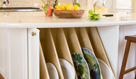
KITCHEN DESIGNKitchen Confidential: Amp Up Your Storage With Pullouts
See 12 types of cabinet pullouts that make your cooking and cleaning items easier to find and use
Full Story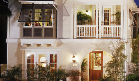
ARCHITECTURETime-Tested, Low-Tech Ways to Cool a Home
People have been beating the heat around the world for centuries without plugging anything in. Could these ideas work for your home today?
Full Story
ENTRYWAYSNew This Week: 4 Smart-Storage Entryways
Architects and designers share details on their solutions for organized entryways and mudrooms uploaded recently to Houzz
Full Story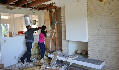
REMODELING GUIDESWisdom to Help Your Relationship Survive a Remodel
Spend less time patching up partnerships and more time spackling and sanding with this insight from a Houzz remodeling survey
Full Story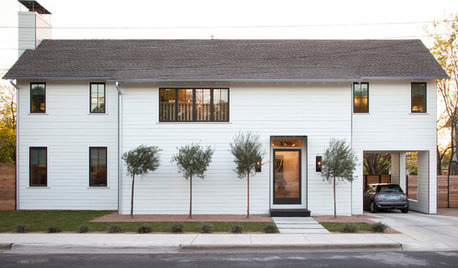
HOUZZ TOURSHouzz Tour: A Modern Take on a Traditional Texas Farmhouse
Contemporary details update the classic form in this Austin home with a kitchen designed for a professional baker
Full Story
BATHROOM DESIGNHow to Settle on a Shower Bench
We help a Houzz user ask all the right questions for designing a stylish, practical and safe shower bench
Full Story
GARDENING GUIDESGarden Myths to Debunk as You Dig This Fall and Rest Over Winter
Termites hate wood mulch, don’t amend soil for trees, avoid gravel in planters — and more nuggets of garden wisdom
Full Story
BATHROOM DESIGNWhy You Might Want to Put Your Tub in the Shower
Save space, cleanup time and maybe even a little money with a shower-bathtub combo. These examples show how to do it right
Full Story
DECORATING GUIDESBulletproof Decorating: Upholstery That Stands Up to Anything
Kids and pets are no match for fabrics as durable as these, which meet higher style standards than ever
Full Story
UNIVERSAL DESIGN11 Ways to Age-Proof Your Bathroom
Learn how to create a safe and accessible bathroom without sacrificing style
Full Story
Ron Natalie
budlite
Related Discussions
Curious about 20 Amp circuit breaker
Q
double pole breaker with different voltages
Q
Will a 40 amp breaker work? baseboard heaters
Q
Two single pole 40 amp breakers not physically tied together?
Q
deckwarehouseOriginal Author
deckwarehouseOriginal Author
budlite
bus_driver
deckwarehouseOriginal Author
Ron Natalie
budlite
kurto
brickeyee
normel
kurto
bus_driver
DavidR
bus_driver
kurto
DavidR
kurto
bus_driver
bus_driver
brickeyee
bus_driver
brickeyee
DavidR