SHOP PRODUCTS
Houzz Logo Print
brooksideiris

Please help me with this K&T/14-3/12-2 mess (long, complicated)

brooksideiris
15 years ago

Current situation: Room has a central overhead light plus 4 side lights wired in series around the perimeter of the room; switches exist at 2 of the 3 doors into the room. Switch at front doorway (into the living room) turns on and off whatever light configuration is set by the switches at the back door. Door from the outside has no switches at all. Door to the back hall has 1 single-pole (?) switch (has 2 side screws) and 1 3-way dimmer. From this door the 4 side lights can be turned on and off independently of the overhead, and all lights can be dimmed. Wiring is an amalgam of K&T, 12-2 and 14-3.

Objective: To leave front doorway switch alone. To move single-pole switch to door leading outside. To change dimmer to a switch, as we now use CFLs, and to move it to the other side the door frame, where it would actually be useful.

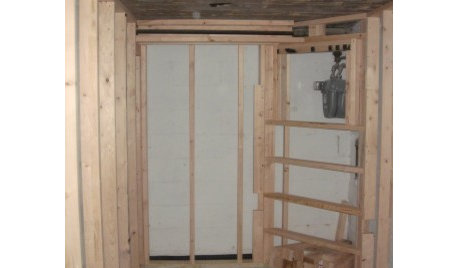
I have photos of junction boxes and switch box but am not sure they are useful. Can post them if you think it would help.

Junction box 1: Negative K&T wire from the lights feeds in the top of the box and out the bottom. Positive K&T wire connects to 14-3 black wire. 14-3 red wire is cut flush with the bottom of the box. 14-3 white wire is capped off.

Junction box 2: Four sets of 12-2, all black wires connected together, all white wires connected together, all ground wires connected together. One of the four feeds up from the basement, from the circuit box. Second 12-2 is used for a line of wall outlets. Third 12-2 is used for a switch and sconce in the back hall; I believe this is 1980s vintage and totally unrelated to the lights in question. The fourth 12-2 feeds into the top of the switchbox in question.

Switch box: Wires coming into this box include the K&T negative and 14-3 from Junction box 1, the 12-2 from Junction box 2 and another 14-3 from the circuit box in the basement. The 3-way dimmer has 3 wires coming out of its back, 2 red and 1 black. First red wire connects with the 14-3 white wire coming from the circuit box. Second red wire connects to the 14-3 black wire coming from the circuit box. The black wire connects to the 12-2 black wire.

There is a black wire coming out of the back of the switch. This has been connected to the red wire of the 14-3 feeding from the circuit box AND to the 14-3 black wire feeding into Junction box 1. The K&T negative wire from Junction box 1 is wrapped around the switchs bottom screw. Nothing is attached to its top screw. The white wire from Junction box 1Âs 14-3 is connected to the 12-2 white wire. IÂm not sure about ground wires.

We originally thought we would follow the previous wiring, but right now we have no faith in it. And we don't care if we lose the capacity to switch the side lights independently of the overhead (we really don't understand how that's working now). Can we make this work with a 3-way and a single-pole switch, given what we want to achieve? I completely don't understand why the 14-3 white wire connects to nothing in Junction box 1 or why the K&T negative passes thru that box. I have no idea why the 12-2 from Junction box 2 is involved at all.

I'm sorry this is so long, and I hope it is clear. Please, please help. TIA

Comments (12)

  • petey_racer
    15 years ago
    last modified: 9 years ago

    Have you considered hiring an electrician to figure this out???

    I am of the strong opinion that K&T is NOT something for a DIY'er to be messing with.

    Also, why start a new thread? Don't you have one going already with replies?

  • brooksideiris
    Original Author
    15 years ago
    last modified: 9 years ago

    I realize it's bad form to start another thread, but time is running out for me (our carpenter is putting up drywall today), and I didn't think this fell under the "basic wiring question" topic. This doesn't seem very basic to me! I also wanted to warn people in the subject line that this post was long an complicated.

    But thank you for your input. It's a little too late for "don't DIY K&T" because that's exactly what the previous owner has done, probably around the early 1980s. I'm doing my best to understand it and just wish I had faith that it had been done correctly. It looks to me like the single-pole switch has been treated like a 3-way? I don't understand what's happened in Junction box 1 or why Junction box 2 is even involved or how any of this relates to the switch at the room's front doorway (whose wiring is behind plaster).

    It would help if I even knew whether to run 14-3 or 14-2 between the door to the outside and the door by the back hall so at least we would have the wiring in the wall before the drywall goes up. And whether we need a single-pole or a 3-way switch at that location. Basically what we're trying to do is to split the contents of that back hall switch between 2 new locations.

  • Related Discussions

    Menu help, please...complications!

    Q

    Comments (21)
    Well, Sandy, welcome to the Cooking Forum, I hope you enjoy it here, as well as enjoying your new kitchen. The brined pork roast recipe is mine, well, it's actually a Cooking Light recipe, but it's become one of my favorites. If I were going to try to hold it in the crockpot, I'd either skip the apple cider reduction, or I'd make extra marinade to warm the pork in so it didn't dry out. Maybe undercook it a little or even cook it completely in the crockpot in the marinade. A couple of small pork loins should cook well, I would think, and you could do the cider reduction ahead of time and just warm it. I'm probably overthinking this, LOL, so here's the recipe. APPLE CIDER BRINED PORK ROAST 3 cups apple cider 3 cups water 1 bay leaf ¼ cup salt 1 tbls black peppercorns 1 tbls coriander seeds 1 2 lb. Pork loin, trimmed 2 cups cider 1 ½ tsp chopped fresh rosemary 1 ½ tsp chopped fresh sage 1/8 tsp freshly ground black pepper Combine the first 6 ingredients in a saucepan and bring to a boil, stirring until salt dissolves. Remove from heat, cool, and pour into a Ziploc bag or container big enough to hold the pork loin. Add pork, seal and let marinate 8 hours or overnight. Preheat oven to 350, bring 2 cups cider to a boil over medium high heat. Boil until cider is thickened and reduced to ¼ cup, about 15 minutes. Set aside. Remove pork from bag or container and discard brine. Place pork on broiler pan or baking dish and lightly coat with cooking spray. Sprinkle with remaining herbs and bake about 1 hour, until pork is done, basting twice with the reduced cider in the last 20 minutes of baking. Remove from oven, baste with remaining cider reduction. Let stand 10 minutes before slicing. Serves 8 Oh, and most importantly, have fun! Another congratulations to your daughter for her big event. Annie
    ...See More

    I'm a mess and way too hung up on labels and rules. Help me!

    Q

    Comments (147)
    Beth, I have been so delighted and educated with all these posts. I love the evolution of your wonderfully charming home! You are an amazing woman! I share several of the decorating dilemmas you've mentioned. My "living room" is about 2' more narrow and 2' shorter than your area. I'm learning a lot from your post. The repurposed gun cabinet idea is absolute genius. Please share a photo when you've installed the shelves and contents. Regarding the non-glare glass for your larger artwork. The price of non-glare glass has become simply ridiculous. I have an entire hallway lined with (Gasp!) a family gallery wall. It includes photos from more than 100 years ago to this year's school pics of the great-nephew. Color, colorized, sepia toned, black and white, all mixed together and mostly in their original mismatched frames. That just about breaks all the rules, but I love my wall. Several of the older photos - Mom's 1954 graduation photo; MIL's 1952 wedding photo, etc. - had plain glass. I can't tolerate the glare either. I made a note in my iPod of all the frame sizes that needed replacement non-glare glass. Every time I'm at a thrift shop or yard sale I check out the "frames" area. You can often find large pictures that may be in horrid frames, but they will have non-glare glass! I buy the frame, take out the glass, and toss the rest. I found one very large print of ballet slippers framed with non-glare that was big enough to cut down into several pieces. It made one 8x10 and three 5x7 pieces of non-glare glass for my wall, all for $1. With their permission, I took the glass out at the shop, tossed the faded print, and re-donated the empty frame back to them.
    ...See More

    Please help!!!! Advice on 1/4 gap between Kitchen Cabinet doors.

    Q

    Comments (5)
    Ha - yes, they deleted their comment, it seems. They told me I didn't deserve new cabinets because of a decision I didn't like and that I tried to put lipstick on a pig or something.
    ...See More

    Please help!!!! Advice on 1/4 gap/reveal btwn Kitchen Cabinet doors

    Q

    Comments (11)
    Hi yes - thank you for the response. Actually, ~50% of the cabinets are brand new custom cabinets. The whole reason I ordered the customs was so that I could get the spacing even, or at least somewhat even. I was told that going with all new semi-custom was not allowed. The Home Depot rep's exact words were "I can't let you do that, you have already paid the deposit". I said I didn't understand because the order hadn't been placed yet, he told me I could change my mind on anything before the order was placed and that I would buy them from Home Depot. He said "Sorry, Home Depot will penalize you a lot of money". But I could do some total customs because it was his dept (i.e. he gets commission). The installation manager told me during the install that they should have never accepted my job as a reface (there were a number of other complications). So I'm not sure what to do now.
    ...See More
  • spencer_electrician
    15 years ago
    last modified: 9 years ago

    I'm an electrician that lives 6 minutes from brookside :) Every house I work on around there is just like yours it seems. So many previous remodels and the wiring always neglected.

  • terribletom
    15 years ago
    last modified: 9 years ago

    You're not going to like this and, truly!, I feel your pain. Nevertheless, the bottom line is that you're in over your head. And if it makes you feel any better, the vast majority of occasional DIYers--even those with considerable basic wiring experience--would be over their heads with this situation.

    I (or others) could shoot from the hip about some of your specific questions. Why is one of the wires of that 14-3 capped off and the other just cut? Perhaps there might have once been a set of 3-way switches that's been re-wired (correctly or incorrectly). Maybe the "electrician" at the time didn't need three wires but happened to have a piece of 14-3 handy. Who knows for sure?

    Without fully mapping out the circuitry and assessing the whole situation, any answer or set of answers would be pure conjecture--potentially dangerous guesswork.

    Moreover, your description of the problem(s) betrays a lack of understanding of the basics of house wiring. My intent is not to insult you. Really! If anything, I admire your two-fisted attack to the problem. And your dilligence in trying to supply details, including pics, is commendable as well. (I wish more posters would supply pictures, BTW.)

    But gazing into j-boxes and trying to account for black wires, red wires and white wires is not enough to unravel this, much less to help develop a plan for re-locating switches and re-wiring the room. And make no mistake about it: that's exactly what is at issue--a rewiring of the room and, perhaps, adjacent dependencies.

    In the best of worlds, you might have been able to do what you set out to do--to move a few boxes, swap out a dimmer for a switch, etc.--using the old wiring as a template. What you encountered is a mixture of modern and K&T wiring that doesn't meet your requirements and is confusing (and possibly even miswired).

    One thing about K&T: If there's any good rule of thumb, it is either to replace it or leave it undisturbed. Where K&T is in working order and appears to be in good shape, it's not an uncommon practice to tie an exisiting K&T leg to a new circuit and that appears to be what happened (mostly?) in 1980. But re-routing and re-working K&T is a perilous business at best.

    To my way of thinking, your best bet is to replace the K&T in its entirety with respect to the circuitry in this room. Since you're apparently "down to the studs and joists", this is probably the time to bite the bullet and do that.

    But the whole K&T can of worms aside, you're planning to move some switch boxes and rework what they control. That raises the issue of "abandonment". The old wiring (i.e., wires to switches, fixtures, etc., that will be moved) shouldn't just be left behind the walls. Those old junction boxes can't simply be drywalled over. They'll either have to be left accessible and covered with unsightly plates or all of the connections will have to be competently moved elsewhere and the old unused wires and boxes removed and/or properly terminated.

    Like I said, it's not what you wanted to hear. But in my judgement, you really do need to call in an electrician pronto.

  • spencer_electrician
    15 years ago
    last modified: 9 years ago

    I could make it there tonight to look at it and my company is working on a brookside area house all week. Do fix it correctly or have someone do it. Not right to hang sheetrock over that mess when it could take a few hours to fix now.

  • pharkus
    15 years ago
    last modified: 9 years ago

    You are DEFINITELY "in over your head" for fixing what's there.

    And "Don't DIY K&T" is damn solid advice unless you're... well, you're not.

    HOWEVER

    I'm not a fan of K&T anyway. Can you rip it out and start over? It would be VERY easy to draw up a PROPER circuit to function as you've described.

    How about just putting a blank cover over the switch you want to move, and running a wire from there to the new location, using the old location as a junction box? That's the only way I can think of to move something you don't understand. Of course, working on ANYTHING without completely understanding it conflicts with my most basic senses, but in your case, it may be an option.

  • brooksideiris
    Original Author
    15 years ago
    last modified: 9 years ago

    Spencer_electrician, thank you for your offer to come over Sunday night to assess my situation (and I'm sorry it's taken me till Wednesday to respond; I've been off-line since then, between my schedule and all of these storms we've had this week--our house has a strict policy of unplugging all electronics during thunderstorms). I've appreciate your offer and have tried to e-mail you thru GW, but without success.

  • brooksideiris
    Original Author
    15 years ago
    last modified: 9 years ago

    Pharkus, my absolute first choice would be to remove the K&T. The 4 sidelights I described are not actually on the plaster ceiling (as is the overhead) but are hanging 6" below it, at the bottom of decorative hollow wooden beams. Even tho they clearly have been fine for 80-some years, it still makes me nervous to have electricity running thru all that wood without the benefit of fixture boxes.

    Because the nearest sidelight is only 2 feet away from the wall containing Junction box 1 and because the K&T disappears into the ceiling very near the wooden beam on which this light hangs, we had hoped we might be able to do away with the K&T for all 4 sidelights. We spent a day gently prying apart the affected beam so we could get a better look at the wiring. Unfortunately, tho, that didn't help. Without tearing apart the ceiling (which we really aren't prepared to do at this time) it's impossible to really tell, but it looks like the exposed K&T connects directly into the overhead (thru at least 3 joists). And of course, it's a fair bet that the wiring to the switch by the front doorway is also K&T--but we don't intend to break into that wall, either.

    As far as moving the switch you're absolutely right: "It would be VERY easy to draw up a PROPER circuit to function as you've described." And in fact, it doesn't even require using the existing switch box as a junction box. Neither of the 2 existing junction boxes need to be moved, just the 14-3 coming thru the floor from the circuit box (which is easy enough to do because all wiring in the basement is exposed). I would expect it to be a matter of drilling holes thru exposed beams, running 14-3, placing a 3-way switch by the door to the outside and a 4-way switch on the other side of the back hall door. Total of three switches, 2 light sources for that room. In my opinion, all of the K&T should be confined to Junction box 1.

    It has never been my intention to wire around the existing circuitry "without completely understanding it." My intention has been to understand it. If you'll notice, my questions have been specific: "Why was the red wire cut off at the bottom of Junction box 1?" "Why is the 14-3 white wire capped off inside Junction box 1?" On the whole, the responses I've gotten here have been of the "don't worry your little head about it" variety, which frustrates me. I understand why: an electrician in Klamath Falls or Kalamazoo doesn't want to be responsible for some anonymous fool in Kansas burning down a house! But whether I hire an electrician or a handyman or diy, I still want to understand this circuit. I want to know if the PO knew what he was doing--because he's done a lot of wiring in this house, and right now I don't have a lot of faith in him.

    Clearly this circuit has functioned property for the last 20 years or so. But I thought a circuit (as in "circle") requires all wires to connect to something, somewhere. In this case, the white wire from the 12-2 connects in the switch box to the 14-3 white wire which is then capped off in Junction box 1. I understand that had 1 K&T wire not been essentially pulled all of the way thru Junction box 1 and connected to the switch, PO would not have had enough white wires to play with in that switch box. I also understand that had he looped the 14-3 white wire thru Junction box 1 to provide his additional wire for the switch box, one of the K&T wires would have been left dangling in Junction box 1, which definitely would have killed the circuit. I also understand that by capping off that white wire, PO has dead-ended the white wire from the 12-2. What I don't understand is why that's ok. Or why there isn't a solution which would have allowed all of the K&T to terminate inside junction box 1.

  • brooksideiris
    Original Author
    15 years ago
    last modified: 9 years ago

    Terribletom, I appreciate your caution in responding, and I thank you for your diplomatic concern for my feelings. I certainly can understand your fear that I might rip haphazardly into wiring I don't fully comprehend, then go about my business till the house burns down. But I've come here to learn, and my skin is thick, so forgive me if I press ahead.

    "I (or others) could shoot from the hip about some of your specific questions." And I thank you for your interpretation of the cut red wire. You apparently are right about the PO using a piece of 14-3 when he actually needed 14-2; had I noticed that the red wire was clipped on the switch box side as well, I would have realized the red was just a short span of dead wire--and that would have answered my question about why it was cut short instead of being capped off like the white wire. And I suspect at some point somebody would have suggested that my confusion about why the PO used a single-pole switch (note my question mark in my initial description) might be because it isn't a single-pole, that perhaps 3-way switches in the 1980s looked like single-pole switches with a wire coming out of their backsides. So that clears up THAT question.

    "Without fully mapping out the circuitry and assessing the whole situation, any answer or set of answers would be pure conjecture--potentially dangerous guesswork." I understand that. And I realize that by describing the circuitry rather than posting my diagram of it I managed to scare and confuse people, possibly making my wiring project sound more complicated than it is. I HAVE mapped out the circuitry and have presented it all here as concisely as I could so that more knowledgeable heads than mine could assess it. The only piece I've left out is the origin of the 12-2 from Junction box 2. I know the wire to the basement has to connect back to the circuit box, but I assume that it also connects to the switch by the front doorway (the one inside the wall that I'm leaving alone)--because it HAS to. For one thing, in order for all 3 switches to work together, that front switch cannot be an island; for another, that switch has to connect to the second light source (whether it be the overhead or the side lights), because I only have 1 set of K&T wiring exposed, and clearly the overhead functions independently from the side lights. I can (and should) go down to the basement and trace that connection. But it has to be there. Otherwise, why involve junction box 2 in this at all?

    "Moreover, your description of the problem(s) betrays a lack of understanding of the basics of house wiring." Could you please elaborate? If it is because I used the terms "positive" and "negative" instead of hot and neutral, I apologize. I'm also aware that I used "beam" instead of "stud" at one point. And, having had my "eureka" moment, I am relieved to realize there are no single-pole switches involved here. I've tried very hard to be clear but know that precise vocabulary is important in technical explanations. I need to know what I'm missing, because I'm obviously not explaining myself adequately.

    "you're planning to move some switch boxes and rework what they control. That raises the issue of 'abandonment'." I am planning to move 2 switches, but I'm not sure I have the wherewithal to rework what they control, nor is that my goal. There will be no abandonment here. I'm not moving either junction box 1 or 2 (nor do I really want to fiddle with their contents)--just including them in my explanation in order to present "the whole situation." I need to place a switch by the door to the outside, connect it to another switch 3 feet away on the same wall (by the door to the back hall), move the 14-3 coming thru the floor from its current location to the new wall, extend the new wiring around the corner back to the 2 junction boxes, insulate the wall with the new switches before the carpenter (he didn't get to that wall last Sunday) drywalls that short section. No drywalling is being done at this time on the wall with the junction boxes.

    "And make no mistake about it: that's exactly what is at issue--a rewiring of the room and, perhaps, adjacent dependencies." But if I don't alter the contents of the junction boxes, I can't affect dependencies, right? The only function coming thru junction box 1 is some of the overhead lighting. I don't believe any of the outlets or the back hall light would be affected by moving the 12-2 out of junction box 2 (which might well be the most sensible thing to do, given how crammed that box is), but right now we intend to leave that box alone--just lengthen the run of 12-2 so it can reach the new switch.

    "But re-routing and re-working K&T is a perilous business at best." I've noticed that mentioning K&T does seem to make folks nervous. I would LOVE to get rid of the K&T in this room, but that's a much bigger project than we can manage at this time. All I want to do is to confine the K&T in junction box 1. And in order to do that, I have to understand what's going on with the "white wire" leg of this circuit. What I want more than anything is to replace the existing mess coming out of the bottom of junction box 1 with a single 14-2 (or 12-2, if that is the better option) and feed it, along with the 12-2 from junction box 2 thru the holes in my studs over to the new switch box locations. But I can't do that until I make sense of the current configuration. I don't own a camera. My DS took the pictures of the existing wiring. Would it help if I asked him to take a picture of the diagram I made in order to explain all this? Would you feel more comfortable if I went down into the basement and traced the path of the 12-2 back to the switch by the front doorway (yes, I know I need to do this anyway--and yes, I KNOW it would make you most comfortable if I said "I'm hiring a licensed electrician")?

  • pharkus
    15 years ago
    last modified: 9 years ago

    brooksideiris, my answer was multipart and you seem to have combined them.

    Capping off unused wires is OK, just because it is.

    How about pulling (fishing) new cables up from the basement for all of the devices?

    As soon as the kid who sleeps in my computer room wakes up so that I can type more without being rude, I'll attempt to analyze and answer your original question. As a nerd who continually attempts to do what "can't be done" with computer equipment, I certainly do know how frustrating it is to ask "how" and receive no answer other than "you shouldn't".

  • terribletom
    15 years ago
    last modified: 9 years ago

    "Moreover, your description of the problem(s) betrays a lack of understanding of the basics of house wiring." Could you please elaborate? If it is because I used the terms "positive" and "negative" instead of hot and neutral, I apologize.

    Yes, I took your use of the terms positive and negative as a definite tip-off. If the terms "hot" and "neutral" were functionally equivalent to "positive" and "negative" for all intents and purposes, then I'd be inclined to chalk this up to a simple difference in terminology and just move on. But they're not. Two hots from different circuits can combine to produce 240V volts instead of 120V and two neutrals from different circuits are not the same as a single neutral on one circuit either. This isn't mere nit-picking.

    Let's back up a bit.

    Junction box 2: Four sets of 12-2, all black wires connected together, all white wires connected together, all ground wires connected together. One of the four feeds up from the basement, from the circuit box. Second 12-2 is used for a line of wall outlets. Third 12-2 is used for a switch and sconce in the back hall; I believe this is 1980s vintage and totally unrelated to the lights in question. The fourth 12-2 feeds into the top of the switchbox in question.

    Without further facts, the usual inference would be that this is a junction box for a 20-amp circuit. That's suggested by the use of #12 wire, but it's by no means a certainty. It is possible that this circuit might be protected by a 15-amp breaker, making the #12 wire simply "overkill". The point is this: Without verifying the entire circuitry, it amounts to an intial hunch--"guesswork", if you will.

    Switch box: Wires coming into this box include the K&T negative and 14-3 from Junction box 1, the 12-2 from Junction box 2 and another 14-3 from the circuit box in the basement. The 3-way dimmer has 3 wires coming out of its back, 2 red and 1 black. First red wire connects with the 14-3 white wire coming from the circuit box. Second red wire connects to the 14-3 black wire coming from the circuit box. The black wire connects to the 12-2 black wire.

    So if I'm understanding this correctly, the 14-3 from Junction box #1 consists of two unused wires (white and red) plus a black which is presumed to be a hot connected to the "positive" (hot?) of a K&T leg. The "other" 14-3 is presumed to come from "the circuit box in the basement".

    Now, please, help me here. What is meant by "the circuit box in the basement" and how was that determined? That second 14-3 sounds, at first blush, more likely to be associated with circuitry for multiple three-way switches. Are you saying it comes from the load center (i.e., the "breaker panel")? It might just be me, but I'm really not getting this.

    Among other things, what concerns me is the connection of #14 wire with that #12. If Junction Box #1 is indeed a branching point for a 20-amp circuit, there's no way that it's safe to connect it to any #14 wire (which is rated for only 15 amps).

    If, as it sounds at first, that lighting circuit served by #14 wire is being fed off a 20-amp circuit, you have a potentially dangerous problem.

    Then later...

    The white wire from Junction box 1s 14-3 is connected to the 12-2 white wire.

    Hmm. This could be the source of the neutral for the entire lighting circuit.

    I have no idea why the 12-2 from Junction box 2 is involved at all.

    Again, and not to insult your intelligence, this really needs to be understood. At this point, you aren't sure where the power comes from and, moreover, you aren't sure whether the lighting circuitry is on a 20-amp or a 15-amp circuit. Mere niceties? I think not.

    And then...

    The only piece I've left out is the origin of the 12-2 from Junction box 2...I can (and should) go down to the basement and trace that connection. But it has to be there. Otherwise, why involve junction box 2 in this at all?

    Indeed. How many circuits are actually involved? What size breaker(s) are used?

    I'm sorry if you took umbrage at the suggestion that you seek professional advice, but these questions would be starting points for an electrician.

  • terribletom
    15 years ago
    last modified: 9 years ago

    erratum: If Junction Box #1 #2 is indeed a branching point for a 20-amp circuit...