


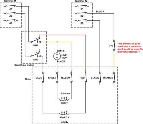
westinghouse electrical motor elctrical wiring problem
yalan liu
6 years ago
last modified: 6 years ago
Sort by:Oldest
Comments (2)
Related Stories

KITCHEN DESIGNThe Most Common Kitchen Design Problems and How to Tackle Them
Check out these frequent dilemmas and expert tips for getting your kitchen design right
Full Story
GREEN BUILDINGGoing Solar at Home: Solar Panel Basics
Save money on electricity and reduce your carbon footprint by installing photovoltaic panels. This guide will help you get started
Full Story
HOME TECHNew Strategies for Hiding the TV
Its easy to be discreet when you've got cabinets, panels and high-tech TV hiders like these
Full Story
LAUNDRY ROOMSA Kitchen Laundry Cabinet Full of Surprises
A little DIY spirit allowed this homeowner to add a washer, dryer, kitchen countertop and dining table all in one
Full Story
LIGHTINGHow to Choose the Right Solar Lights
Learn about different types of outdoor solar lights, where to use them and why you might want to avoid the bargain bin
Full Story
MORE ROOMSWhere to Put the TV When the Wall Won't Work
See the 3 Things You'll Need to Float Your TV Away From the Wall
Full Story
HOME TECHLove Your TV but Not the Way It Looks? Here’s How to Hide It
See the clever new ways designers are concealing that big, blank TV screen
Full Story
HOME TECHWi-Fi: What It Is and How to Make It Work Better in Your House
As more devices rely on this technology in the home, it’s good to be prepared
Full Story
KITCHEN DESIGNHouzzers Say: Top Dream Kitchen Must-Haves
Tricked-out cabinets, clean countertops and convenience top the list
Full Story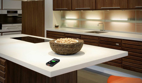
HOME TECHComing Soon: Furniture That Charges Your Phone
Countertops, tables and home appliances with wireless charging capability mean less clutter — and zero effort powering your phone
Full Story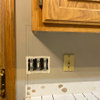

DavidR
randy427
Related Discussions
Electric Wiring on my Milwaukee Grinder Question
Q
coil problem on B@S motor
Q
aeg sic 90 range wiring problem - please help
Q
Ceiling elctrical box required for AC smoke alarm?
Q