


Fisher Paykel GWL11 diverter valve always off, bad controller? Again?
northbear
7 years ago
Sort by:Oldest
Comments (4)
Related Stories
REMODELING GUIDES7 Bad Things Your Home May Be Hiding
What you don't know about your home could cost you during a remodel. Here's what to plan for
Full Story
SAVING WATER11 Ways to Save Water at Home
Whether you live in a drought-stricken area or just want to help preserve a precious resource, here are things you can do to use less water
Full Story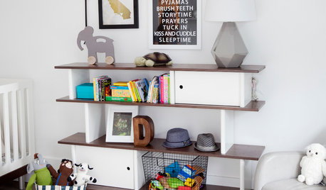
KIDS’ SPACES15 Tips for Small-Space Living With Baby
Keep your wee one's stuff under control and your nerves unfrazzled with these space-saving storage and baby-gear ideas
Full Story
UNIVERSAL DESIGN11 Ways to Age-Proof Your Bathroom
Learn how to create a safe and accessible bathroom without sacrificing style
Full Story
REMODELING GUIDESSurvive Your Home Remodel: 11 Must-Ask Questions
Plan ahead to keep minor hassles from turning into major headaches during an extensive renovation
Full Story
LIFE7 Things to Do Before You Move Into a New House
Get life in a new house off to a great start with fresh paint and switch plates, new locks, a deep cleaning — and something on those windows
Full Story
BATHROOM DESIGNConvert Your Tub Space to a Shower — the Fixtures-Shopping Phase
Step 2 in swapping your tub for a sleek new shower: Determine your mechanical needs and buy quality fixtures
Full Story
HOUZZ TOURSMy Houzz: Industrial-Edged Comfort in Pittsburgh
Copper, cantilevers and a cat named Mr. Martin come together in this contemporary homage to regional style
Full Story
GREAT HOME PROJECTS25 Great Home Projects and What They Cost
Get the closet of your dreams, add a secret doorway and more. Learn the ins and outs of projects that will make your home better
Full Story
BATHROOM DESIGN18 Dream Items to Punch Up a Master-Bath Wish List
A designer shared features she'd love to include in her own bathroom remodel. Houzz readers responded with their top amenities. Take a look
Full Story

dadoes
northbearOriginal Author
Related Discussions
Fisher Paykel GWL11 not filling in rinse cycle
Q
Fisher and Paykel GWL11 Top Loading Washer
Q
Fisher Paykell GWL11 stuck in code 49
Q
Fisher Paykel GWL11 short circuit
Q
Rick Brown
northbearOriginal Author