


Main breaker panel as subpanel
jay_haitch
15 years ago
Featured Answer
Sort by:Oldest
Comments (39)

southhouse
15 years agoRelated Discussions
Mounting Sub-panel next to Main Panel - space requirements?
Comments (7)Thanks for everyone's input. My main panel has 30 spaces and allows a maximum of 40 circuits. It already has the full complement of slimline breakers and is maxed out at 40 circuits by the builder. I'll need to move a few circuits over to the sub-panel to make room for the double pole 70 amp feeder breaker. By the way, the main panel is rated at 200 amps and I calculate my current home load at 87 amps, so I have plenty of capacity available for the 40 or so amps I intend to use from the sub-panel. Dave...See MoreWhole house plan(Main and sub-panels)
Comments (3)Even with gas heat, that's a lot of A/C you've got there, almost 110A worth on it's own. Did you do a proper load analysis? I've heard of outside panels in warm places, but the rather "tropical" nature of Louisiana makes me nervous. I won't screw with 30 circuit panels. What's the point. THe delta for 42 is small and you always have issues with spaces. There's tons of special circuits that need to be addressed. I recommend you get someone who has a clue about things draw up your electrical plans at least. You size breakers for the wire, NOT the other way around. WIre sizes depend on the type of wire, the ampacity required, and the length of the run. Larger feeders tend to be done with aluminum just for cost practicality. There's no problem with aluminum of feeders/services provided they are installed PROPERLY. You can wire everything with 12 G (that doesn't need more than 20A) if you like. Makes things more convenient, especially if you've got longer runs....See MoreConnecting Subpanel to Main Panel
Comments (2)Either bare or green is fine. Given the short run, I'd just run a grounding conductor between the two respective ground terminals. You only need a #10 ground here. You only need #6 for the feeder conductors as well....See MoreSub-Panel breakers trip on load
Comments (8)Thanks for answering the 220 question although the wires going out to the garage probably won't support it. The feeder wires only appear to be either 10 or 12 gauge. I'll need to pull the panel cover off again to see for certain. The line run from main panel to sub panel is only about 40 feet, going underground from the basement and coming up into the detached garage. An added twist is that prior to my ownership, the dirt basement craw-space was the neighborhood cat toilet. A junction box for the garage circuit is laying on the dirt floor and wires go from there underground into the dirt and down and out. The box is eroded from acid in the cat pee and in some places, the armored cable is completely eroded through and only the wires are left exposed in their plastic wrapper. I haven't had the opportunity to tackle that one yet nor have I seen how bad things are inside the box. It may be playing a role with the current loss theory. Fixing that whole mess is another problem in of itself as I don't have any room to play with extra wire. The junction box is already on the ground in the dirt. And, they seem to have just run armored cable into the ground but there is conduit coming up in the garage so it must meet up with it somewhere. A mess, but fairly typical for this 1896 home....See Morejay_haitch
15 years agojmvd20
15 years agojay_haitch
15 years agopharkus
15 years agojay_haitch
15 years agoleonj
15 years agopetey_racer
15 years agoleonj
15 years agopetey_racer
15 years agojmvd20
15 years agoleonj
15 years agoleonj
15 years agoleonj
15 years agopetey_racer
15 years agohendricus
15 years agoRon Natalie
15 years agohendricus
15 years agoMister_Mister
13 years agobrickeyee
13 years agoMister_Mister
13 years agoRon Natalie
13 years agobrickeyee
13 years agospencer_electrician
13 years agoemailplaces_unkown_com
12 years agoRon Natalie
12 years agobrickeyee
12 years agoemailplaces_unknown_com
12 years agobrickeyee
12 years agoMister_Mister
12 years agobrickeyee
12 years agoMister_Mister
12 years agowolf_kathlean_gmail_com
12 years agoRon Natalie
12 years agoJay_Pryorelectric_com
12 years agobrickeyee
12 years agoRon Natalie
12 years agoenigma_2
12 years ago
Related Stories
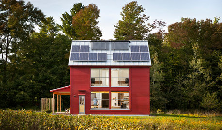
GREEN BUILDINGGoing Solar at Home: Solar Panel Basics
Save money on electricity and reduce your carbon footprint by installing photovoltaic panels. This guide will help you get started
Full Story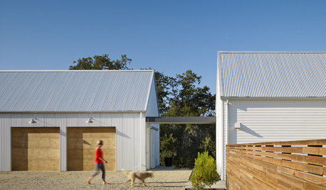
ARCHITECTUREDesign Workshop: Explore the Magical In-Between Spaces
Create new experiences inside and out by separating your main house from the guest suite, workshop or pool house
Full Story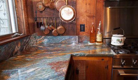
MY HOUZZMy Houzz: Barn Wood Touches for a New England Home
Rustic charm and personality define this family’s traditional Cape Cod home
Full Story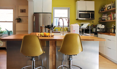
HOUZZ TOURSMy Houzz: Color and Creativity Energize a Midcentury Home
Vintage furniture, fearless colors, artwork and custom touches give a Montreal home a bright, eclectic personality
Full Story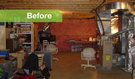
BASEMENTSBasement of the Week: Movies, Workouts and Billiards
Family togetherness moves to a whole other level with a remodeled basement designed to appeal to all
Full Story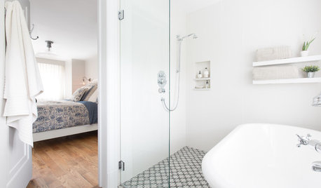
BATHROOM DESIGNSweet Retreats: The Latest Looks for the Bath
You asked for it; you got it: Here’s how designers are incorporating the latest looks into smaller master-bath designs
Full Story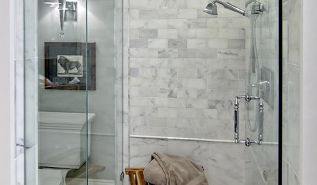
BATHROOM DESIGNHow to Settle on a Shower Bench
We help a Houzz user ask all the right questions for designing a stylish, practical and safe shower bench
Full Story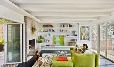
MOVINGHome-Buying Checklist: 20 Things to Consider Beyond the Inspection
Quality of life is just as important as construction quality. Learn what to look for at open houses to ensure comfort in your new home
Full Story
BATHROOM DESIGNDreaming of a Spa Tub at Home? Read This Pro Advice First
Before you float away on visions of jets and bubbles and the steamiest water around, consider these very real spa tub issues
Full Story
KITCHEN DESIGNThe 4 Things Home Buyers Really Want in Kitchen Cabinetry
For the biggest return on your kitchen investment, you've got to know these key ingredients for cabinetry with wide appeal
Full Story

jmvd20