


tracing out membrane buttons
woodturner79
12 years ago
Featured Answer
Sort by:Oldest
Comments (19)

kurto
12 years agoRon Natalie
12 years agoRelated Discussions
how long after pipping should they be out?
Comments (55)This has been the most helpful discussion. I'm hatching turkeys. 1st one was successful. I noticed my heat temp had dropped to 95 due to kids and grandkids opening by setting knob on top. So i bumped it back up. Waiting on 2nd one. But it's different. Yellow yolk bubbles coming out of piping hole. I have taken a Qtip and wiped outside away quickly and replaced lid. Little guy is breathing and chirps some. I'm a little worried about the yellow ooz. There is no blood so that's a plus. Any comments or help for me or my little gobblers?...See MoreOK -- I'm grossed-out at this
Comments (37)The subject matter does not bother me. We really ought to be talking about things. Death is a part of life that, in our kind of culture, is swept under the rug and kept as unobtrusive as possible. But we will all face it. We ought to know our choices and make the best one. Both for burial and what comes after death. That's an interesting proposition. Truly, that's what is supposed to happen to bodies; decompose and be re-used. But I probably would not go that way myself. There is something to be said for traditional dignity and teaching the young that life is more than just recycled chemicals. However, I can easily see that if someone believes that's all human life is, it would be a logical next step. There are a couple of great books I have, "Caring for Your Own Dead" and "The American Way of Life and Death". Both of these are eye openers on the funeral industry and how to not only save money, but dignity. Thinking of donating your body to science? "Stiff; the Curious Lives of Human Cadavers" might change your mind, if you have the idea that your body will lay on the table to be examined in med school. Most cadavers are used in very... unexpected ways. As for me, I want a simple hole dug on my land, wrap my night gowned body in a simple sheet the same day I die. Cover me with a mound of dirt and walk away. I'm not there. Don't come and visit my grave. I'm not there and I'll be really mad at the time and tears anyone wasted visiting a storage pit. If the curious eyes of people make them feel the need to do SOMETHING, they can plant a Rose of Sharon bush on top. That's a nickname for the One who has victory over death and freed me from the grave. And I want a HUGE party thrown. Lots of food, lots of singing, lots of dancing and joy. I'll be seeing them soon. :o)...See Morebuttons on your cards?
Comments (2)Another list!! I'm in hog heaven!!...See MoreTracing doorbell wires behind wall
Comments (23)I've just come back from the basement. I was exploring the area right under the doorbell buttons on the first floor. I found the transformer! It's actually above one of the circuit breaker boxes in the basement immediately adjacent to mine. Our basement is divided into 4 sections. There are 6 condo units on my half of the condo building. This means that there are 2 hallways. Each hallway has 3 units in a vertical row. When I went to the basement and checked under the area where the doorbell buttons are, I noticed 4 wires going in one direction and 4 wires going in another direction. I didn't understand this since I'd assume there would be 6 wires in total. Do you know why this is the case? Is one wire for the transformer? In any case, the bunch of wires for my row of units went a short distance along the basement wall then entered the floor board above the basement. When I went to the hallway, above the basement and approximated where the wires would come out from, it seemed to be inside the wall that divides the two vertical hallways (with 3 condos each). What this means is that the wires probably travel upward and branch off into their respective units. In my case, since I'm on the top floor (3rd) I hope they come up to the attic for this is the only way I'll be able to spot them. My next goal is to go back to the blown-insulation filled attic then check the area that is vertically above the spot in the basement where the wires enter the floorboard. Below are some photos. The first one shows the wires coming from the area below the doorbell buttons in the basement. The second one is of the 3 wires joining together with a 4th one that comes from the transformer. The third one shows the transformer (above the circuit breaker box). Now if I can only find the wires that are hopefully above my 3rd floor condo (in the attic)......See Morebrickeyee
12 years agowoodturner79
12 years agoyosemitebill
12 years agowoodturner79
12 years agoRon Natalie
12 years agowoodturner79
12 years agobrickeyee
12 years agowoodturner79
12 years agobrickeyee
12 years agoRon Natalie
12 years agowoodturner79
12 years agoyosemitebill
12 years agobrickeyee
12 years agobrickeyee
12 years agowoodturner79
12 years ago
Ross W
3 years ago
Related Stories

ARCHITECTUREHave Your Flat Roof and Your Snow Too
Laboring under the delusion that flat roofs are leaky, expensive and a pain to maintain? Find out the truth here
Full Story
GARDENING GUIDESSouthern California Gardener's September Checklist
Before prime planting time, clean out the old garden, prepare for the new, and dream up ideas for fall flowers and veggies
Full Story0

EVENTS12 Must-See Art and Design Events This January
Get out and get inspired! See what’s on the Houzz creative calendar in the new year
Full Story
DIY PROJECTSMake a Gorgeous (Cheap!) Pillow Using Vintage Clothes
With secondhand fabric and a steady hand on the sewing machine, your pillow choices are endless
Full Story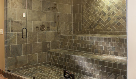
SHOWERSSteam Showers Bring a Beloved Spa Feature Home
Get the benefits of a time-honored ritual without firing up the coals, thanks to easier-than-ever home steam systems
Full Story
DIY PROJECTSTurn a Shipping Pallet Into a Stylish Ottoman
Get the step-by-step instructions for upholstering your own mod living room centerpiece
Full Story
FLOORSHow to Get a Tile Floor Installed
Inventive options and durability make tile a good choice for floors. Here’s what to expect
Full Story
HEALTHY HOMEWhat You Need to Know About Dust and How to Fight It
Breathe easier with these 10 tips for busting mites, dander and other microscopic undesirables
Full Story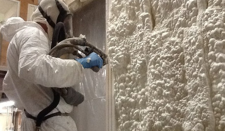
MATERIALSInsulation Basics: What to Know About Spray Foam
Learn what exactly spray foam is, the pros and cons of using it and why you shouldn’t mess around with installation
Full Story
BATHROOM DESIGNConvert Your Tub Space to a Shower — the Fixtures-Shopping Phase
Step 2 in swapping your tub for a sleek new shower: Determine your mechanical needs and buy quality fixtures
Full StorySponsored
More Discussions

woodturner79Original Author