


wiring for three way light switches
unixisgoodforyou
16 years ago
Sort by:Oldest
Comments (30)
Related Stories

LIGHTING10 Ways With Wall Lights That Don’t Need to Be Wired In
Learn how to add illumination to your home without carving into the walls
Full Story
DECORATING GUIDESHomeowners Are Flipping for Push-Button Light Switches
Button-style switches are hot off the presses again, making news in new homes and antique remodels
Full Story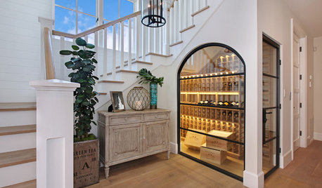
LIGHTINGWhat to Know About Switching to LED Lightbulbs
If you’ve been thinking about changing over to LEDs but aren't sure how to do it and which to buy, this story is for you
Full Story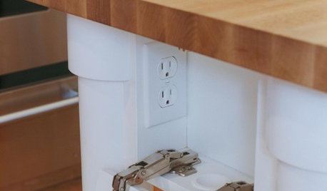
KITCHEN DESIGNHow to Hide Those Plugs and Switches
5 ways to camouflage your outlets — or just make them disappear
Full Story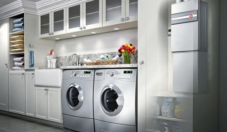
GREAT HOME PROJECTSHow to Switch to a Tankless Water Heater
New project for a new year: Swap your conventional heater for an energy-saving model — and don’t be fooled by misinformation
Full Story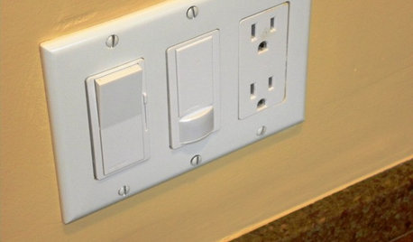
GREAT HOME PROJECTSHow to Install a Dimmer Switch
New project for a new year: Take control of your lighting to set the right mood for entertaining, dining and work
Full Story
DECORATING GUIDESSwitching Up a Colonial Home to Suit a Modern Family
Floor plan labels are thrown out the window as a designer helps a family shape rooms to fit the way they live
Full Story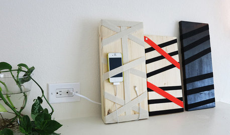
DIY PROJECTSHide All Those Wires in a DIY Charging Station
Keep your gadgets handy and charged with a flexible storage board you can design yourself
Full Story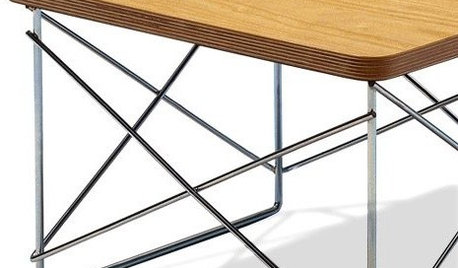
FURNITUREModern Icons: The Eames Wire Base Table
Simple modern table is light and versatile enough for every room in the house
Full Story
GARDENING GUIDESHow to Switch to an Organic Landscape Plan
Ditch the chemicals for a naturally beautiful lawn and garden, using living fertilizers and other nontoxic treatments
Full Story

normel
bus_driver
Related Discussions
Light flickering on a three way switch
Q
two three-way switches with three lights in between
Q
3 way switch wired to control 2 fans, light and fan
Q
Three way switch fed from light with two hots?
Q
texasredhead
unixisgoodforyouOriginal Author
bus_driver
joed
normel
hendricus
bus_driver
texasredhead
normel
bigbird_1
bus_driver
texasredhead
normel
texasredhead
bigbird_1
joefixit2
unixisgoodforyouOriginal Author
bus_driver
hendricus
bus_driver
blackadder34
bus_driver
normel
bus_driver
unixisgoodforyouOriginal Author
hendricus
texasredhead
normel