


The Article about Battery Level Indicator I Like
afanda ling
6 years ago


Sort by:Oldest
Comment (1)
Related Stories

FUN HOUZZEverything I Need to Know About Decorating I Learned from Downton Abbey
Mind your manors with these 10 decorating tips from the PBS series, returning on January 5
Full Story
LIFEWhat I Learned About Moving a Loved One to a Retirement Home
Setting up an elderly family member’s apartment in an assisted-care facility is a labor of love for this Houzz writer
Full Story
DECORATING GUIDESHouzz Tour: Much to Like About This Traditional Beauty
New elements mix well with old in a New Jersey family’s elegant and comfortable colonial revival home
Full Story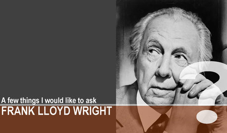
COFFEE WITH AN ARCHITECTA Few Things I Would Like to Ask Frank Lloyd Wright
It could take a lifetime to understand Frank Lloyd Wright's work — less if we had answers to a few simple questions
Full Story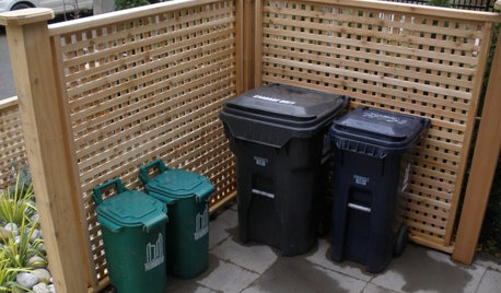
THE POLITE HOUSEThe Polite House: What Can I Do About My Neighbors’ Trash Cans?
If you’re tired of staring at unsightly garbage way before pickup day, it’s time to have some tough conversations
Full Story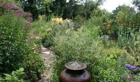
GARDENING GUIDESHow I Learned to Be an Imperfect Gardener
Letting go can lead to a deeper level of gardening and a richer relationship with the landscape. Here's how one nature lover did it
Full Story
LIFEThe Beautiful Thing About Dad's Chair
My father had his own spot in the house. His father had his own spot. Now I have mine
Full Story
BATHROOM MAKEOVERSWhat I Learned From My Master Bathroom Renovation
Houzz writer Becky Harris lived through her own remodel recently. She shares what it was like and gives her top tips
Full Story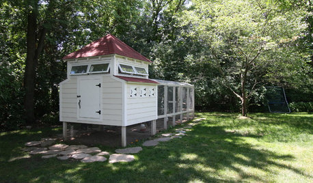
FARM YOUR YARDRaise the Roost: You Won’t Believe These Next-Level Chicken Coops
With designs as fresh as the eggs they house, these 8 creative coops are worth crowing about
Full Story
WORKING WITH PROSEverything You Need to Know About Working With a Kitchen Designer
Enlisting an experienced pro can take your kitchen project to the next level. Here’s how to make the most of it
Full StorySponsored
jemdandy
Related Discussions
About Fall Color Chemistry Easy Read Article
Q
battery indicator light on but car starts fine?
Q
interesting article about cilantro
Q
question about tirm levels in an older home
Q