


What are Municipal water pipes made of?
chamsou
8 years ago
Featured Answer
Sort by:Oldest
Comments (7)

rgreen48
8 years agolast modified: 8 years agoRelated Discussions
water pipe break - water everywhere....
Comments (6)Dave: I am a contractor in the restoration business for decades and seen thousands of residential and commercial insurance loss claims. I have handled losses from less then a thousand dollars to losses in the millions. IMO too many property owners trust their insurance company to properly handle their claim. Most insurance companies, (not all) have contractor programs for one reason and one reason only, to control their costs. I can only count on one hand the number of insurance companies that really care about doing whatever it takes to satisfy their customer after a claim. When you file an insurance claim, its parallel to filing a claim in court demanding money for damages. When in court, both parties have their own independent representation to protect their interests. In the insurance industry, (and the only industry I know of) most property owners allow the other party to represent their interests. Who do you think the insurance adjustor is going be devoted too, you or the company who trained them and signs their paycheck? For the most part, insurance companies donÂt train adjustors how to properly mitigate or repair property damage. Adjustors are not highly trained in construction and if they do have some construction skills they were not taught by the insurance company. Insurance adjustors are trained how to manage the claim. Insurance companies train their adjustors how to negotiate. The primary job of the adjustor is to limit the insurance companyÂs costs. PERIOD I could spell out volumes of other concerns to look for but IÂm sure you want to know how your property should be restored. Your description of how they are drying your property is my first big red flag. That process of pulling pad and floating carpet used to be the industry protocol years ago. Some insurance companies prefer their contractors still do it this way. If my company is involved in a clean water loss, we never dry a property in this fashion anymore. We stopped this process about five or six years ago. We follow our proven industries protocol, not what the insurance companies want or what a franchises home office dictates. The proper way to mitigate a clean water loss is to extract the water from the carpet and pad using the proper equipment. This equipment is not just a wand and extractor but a heavily weighted piece of equipment that will removed most of the water from the carpet and pad while itÂs in place. This equipment is rather expensive and some restoration companies still havenÂt made the investment. Placing a fan under the carpet can stretch the carpet and do other damages that only show up well after the contractor has gone down the road. Think about this, after a clean water loss, the drywall, plywood sub floor, wood framing carpeting and padding get wet. The carpet and padding is the most porous and by far the easiest to dry. YouÂre not removing all the other materials, why remove the material thatÂs the easiest and fastest to dry? If a water loss is properly extracted and dehumidification and air movement is properly set up and no vapor barriers are present, all standard building materials will be dry in 3 days. My company guarantees it. There are some materials such as hardwood flooring, plaster and concrete to name a few that can take longer to dry. The other red flag from your post is the area was 90 degrees and days later the carpet and pad was still wet. This is the perfect environment for mold growth. If the carpet and pad are still wet this far into the loss, you have no choice but to get ride of it and check for mold problems. If the carpet has been wet this long there is a good chance the backing is delaminating anyway. Make sure if any exterior walls were saturated that the insulation behind those walls are not wet. Most of the time, insulation will need to be removed to dry properly. If any vapor barriers are in place such as gloss paint will also inhibit proper drying. If you want to talk this weekend, send me your contact information to mas5461@yahoo.com and I will call or email you....See MoreWater Pipes keep clogging up
Comments (14)Umm. I would guess that OSHA would be interested in these pics. People are injured or die all of the time when the sides of a hole cave in and trap the worker. They suffocate because the dirt around them prevents them from inhaling - even if their head is above ground. They also suffer oxygen deprivation to the limbs because blood flow is cut off. To prevent that, various methods are used including a metal structure lowered into the hole to prevent it from collapsing while the worker is below grade. Trenches over 5 feet deep must be supported in such a manner. To be down 12 feet with no protection is major stupidity and the supervisor should be called out on this. Really - make an issue of it... Send the photos to OSHA and the head of the department. The next guy in the hole may not be so lucky. Education and enforcement is the only way not to end up with dead workers. Here is a link that might be useful: Trench OSHA Quick Card...See Morecorroded water supply pipe
Comments (8)Just a few terms to wok with. main - the pipe that the water system uses to supply water to your area, normally 6 inch or 8 inch pvc or iron located on the right of way or under the street service connection - the small piping that connects the water main to the customer's water meter, normally 3/4 to 1 inch copper or HDPE tubing meter - the device that tells the water works how much water you used so they can bill you for it backflow preventer - a check valve located between the house and meter that prevents water from leaving the house and re entering the water main during a main break or flushing supply line - the piping that carries the water from the meter to the building, this belongs to the customer Also, when you replace the parts of the lines that are restricted you can get some leaks in weakened parts of the plumbing system due to higher flow and pressure....See MoreHouse water supply pipe size
Comments (8)Far too often people get one of those silly little pressure gages that have a female hose thread adapter and attach that to a hose bib or laundry faucet and blindly assume the pressure they see is the actual working pressure of their system but such is not the case. When you attach one of those gages to a faucet then open the faucet to take the reading the gage is blocking the outlet thus for all intents and purposes they are still recording the pressure in a closed system. The basic laws of physics state that the pressure will remain constant at all points in a closed system however, the moment that we open a faucet and allow water to flow the pressure throughout the system immediately drops to "Dynamic Head Pressure" or more commonly stated as "Working Pressure." Dynamic head or Working head pressure is Static Head pressure minus "Friction Head Loss" and "Vertical Static Head Loss". Water physically weighs 0.434lbs per vertical inch column therefore to compute vertical static head loss we must measure the actual vertical rise from the point where we measure the pressure to the point of demand. As an example; let us assume a two-story house where the water line enters the basement near the floor and the shower is on the second floor. Typically we would have an 8 rise to the ceiling plus 1 for the floor joists and flooring material on the first floor, 8.5 to the ceiling and another 1 for floor joists and flooring material to the second floor and finally a 5.5 rise to the showerhead for a total vertical rise of 24Â. The vertical static head loss from the main water shutoff valve to the showerhead would then be 0.434psi x 24 = 10.4psi loss. Now assume that we measure the pressure at the main water shutoff valve and we get 45psi. This means that the absolute maximum pressure at your showerhead would then be 45psi minus 10.4psi = 34.6psi. From this we would then need to subtract friction head loss to determine the actual pressure at your showerhead. In the original post they stated that the pressure and volume is fine when only one faucet is opened but it decreases rapidly as two or more demands are opened. That is because "Friction Head Loss" increases dramatically as the velocity of flow increases. By example, let us continue to examine what happens if just the shower is used. Let us assume that in addition to the 24 vertical rise there is a 10 horizontal offset from where the supply line enters the basement to where it rises up to the shower therefore the total length of the line inside the house from the water main to the shower is 24 vertical plus 10 horizontal for a total of 34Â. (Technically we would need to also add in the fitting insertion losses but for now we will disregard them). The post states that they have a ¾" supply line that is 200 long. Let us assume the line to the shower to be a ½" line 34 long and the shower is rated for a flow rate of 2.5gpm. We measured 45psi at the main water shutoff valve and as was previously stated the pressure is constant at all points in a closed system so it then stands that the pressure at the prime mover (municipal main) is also 45psi however when flow begins friction head loss also begins at the prime mover. The post states that the existing supply line is ¾" and let us assume it is continuous roll PE-SDR pipe (black poly-which has one of the lowest friction loss factors). Consulting the PE-SDR friction loss table we find that at 2.5gpm the loss is 1.5psi/100ft and we have 200 so the loss is 3psi from the municipal main to the main water shutoff valve. Assuming the ½ line to the bathroom is copper we then consult the type L copper pipe friction head loss table and find that for the 34 run from the main to the showerhead we have a net loss of 0.118psi/foot x 34 = 4.02psi so at 2.5gpm the total friction head loss is 3psi + 4.02psi = 7.02psi (round off to 7psi) The static head pressure was 45psi and dynamic head pressure is static head pressure minus vertical static head loss + friction head loss so the actual pressure at the showerhead is 45psi  7psi  38psi. That is not bad pressure if we could be assured that no one would turn on any other fixture while we are taking our shower however the plumbing code requires that when we design a water supply system it must be capable of maintaining certain minimum pressure standards in a worst-case scenario where all the demands in the structure are open simultaneously. Under the UPC we would use the FU (Fixture Unit) method as I described in my previous post whereas under the IRC we use a minimum gpm rate for each fixture. Both methods will ultimately arrive at the same solution so for simplicity let us use the IRC demand rates here. Bob sent me an email stating that he has the following fixtures: 4 sink faucets 2 toilets 2 bathtubs 1 shower 3 hose bibs outside When I examined the list I was a bit confused. With 2 toilets I am assuming he has two bathrooms and one of the sinks is obviously a kitchen sink so I am guessing that he has a master bath with both a tub & a shower and perhaps 2 lavatories but on the other hand one of the sinks could also be a laundry sink. From IRC table 2903-1 we get the following minimum pressure and flow rates to each fixture. BathtubÂÂÂÂÂÂÂÂ.4gpmÂÂ8psi Shower (temp controlled)Â3gpmÂÂ..20psi LavatoryÂÂÂÂÂÂÂ..2gpmÂÂ.8psi Kitchen sinkÂÂÂÂÂÂ.2.5gpmÂ.8psi Water Closet(tank type)..Â3gpmÂ....8psi Laundry hookupÂÂÂÂ..4gpmÂÂ8psi Hose bib #1ÂÂÂÂÂÂ.5gpmÂÂ8psi Hose Bib#2ÂÂÂÂÂÂ.5gpmÂÂ.8psi TOTAL LOADÂÂÂÂ28.5gpm Although not mentioned, if he has a dishwasher that would add another 2.75gpm. Now let us examine the Friction loss table once again. With a flow rate of 28gpm the velocity of flow through his ¾" PE-SDR line is 16.82feet/sec or more than 4 times the maximum allowable 4ft/sec and at this rate the line will exhibit severe pipe wall and fitting erosion resulting in premature line failure and the friction loss is 59.41psi/100 of pipe. Given that his line is 200 long @ 28gpm the total friction head loss is 2x 59.41psi = 118.82psi thus the friction head loss is more than twice the supply pressure of 45psi and with all fixtures open at best he would barely get a trickle of water and no noticeable pressure. Even increasing to a 1" line would still result in a 36.5psi friction head loss from the municipal main to the main water shutoff at the house. On the other hand if the line from the main to the structure was increased to 2" the friction head loss through the supply line would be reduced to 1.36psi and the resultant pressure at the house main shutoff valve would be 45-1.36= 43.64psi which remains slightly above the code minimum supply pressure of 40psi....See More
chamsou
8 years agoklem1
8 years ago
Vith
8 years agolast modified: 8 years agogeoffrey_b
8 years agoweedmeister
8 years ago
Related Stories
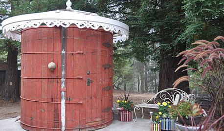
OUTBUILDINGSSee an Outdoor Bathroom Made From a Water Tank
This repurposed fixture in a California backyard is now the owners' favorite bathing spot
Full Story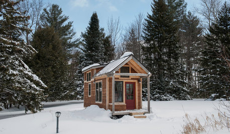
TINY HOUSESHouzz Tour: A Custom-Made Tiny House for Skiing and Hiking
Ethan Waldman quit his job, left his large house and spent $42,000 to build a 200-square-foot home that costs him $100 a month to live in
Full Story
KITCHEN DESIGNKitchen of the Week: A Burst Pipe Spurs a Makeover
Once dark and clunky, this compact kitchen in a 1962 ranch is now light, bright and cheerful
Full Story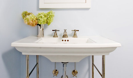
BATHROOM DESIGNSink Pipes Worth Seeing
Decorative Options Let You Get Creative With Those Fixtures Under the Sink
Full Story
LIFEThe Polite House: How Can I Tell a Construction Crew to Pipe Down?
If workers around your home are doing things that bother you, there’s a diplomatic way to approach them
Full Story
BEDROOMS13 Simple Steps to a Perfectly Made Bed
Drift off to dreamland in a delightfully soothing, artfully dressed bed worthy of a posh hotel
Full Story
LANDSCAPE DESIGNHow to Move Water Through Your Landscape
Swales, underground pipes or a mix of both: There’s more than one way to distribute water in the garden
Full Story
LANDSCAPE DESIGNHow to Design Your Landscape to Slow Down Water
Putting the brakes on stormwater runoff is the first step in sustainable water design
Full Story
GREEN BUILDINGJust Add Water: Rain Barrel Magic
Take your rainwater storage from practical to beautiful with a new breed of design-friendly rain barrels
Full Story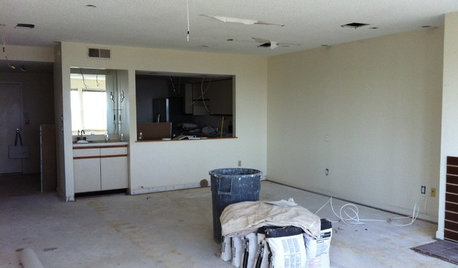
DISASTER PREP & RECOVERYRemodeling After Water Damage: Tips From a Homeowner Who Did It
Learn the crucial steps and coping mechanisms that can help when flooding strikes your home
Full Story
klem1