


How much is too much (electrical)
thecause16
16 years ago
Featured Answer
Sort by:Oldest
Comments (53)

tom_k_de
16 years agolast modified: 9 years agorcmoser
16 years agolast modified: 9 years agoRelated Discussions
How much flux is too much flux ? And some more ??
Comments (20)In regards to Brickeyes comments on technology, I could not agree more. I think Brickeye and I are about the same age (59) and thinking back I am amazed at what was science fiction when i was a kid but what is commonplace today. Just a few examples" When we were in school a word processor was a manual device made of wood and graphite with an eraser on the opposite end..LOL. When they landed men on the moon complex math was still being done on slide rules, now I have a wristwatch with a built in calculator that can perform functions that were unheard of on mainframe computers in the early to mid 60's. In Jr.High school every kid dreamed of owning a 6 transistor pocket AM radio receiver. (I actually acquired one by caddying at the local golf course for the whole summer to earn the necessary $36 to buy it.) minimum wage was $1.55 and top union scale was $5/hr. Color TV was still in its infancy and most stations did not broadcast color until the early 60's. FM radio was solely classical and elevator music and of very little interest to young people. When I entered the Air Force in 1966 I worked with a Univac 1066-II mainframe computer system that had a hard drive which was 10 feet long and weighed over 3 tons, yet it only had 66megs of memory, by contrast I have 80 gigs on this desktop and 60gigs in my laptop, both of which are obsolete by state of the art standards. While on the subject of laptops, the only laptops devices we had then was a TV tray for dinner....LOL Cordless tools were totally unheard of. State of the art automotive safety was a padded dashoard and a seat belt. I remember when they came out with a digital clock that had rotating flip cards with the numbers on them and we thought that was the rage. For all you Star Trek fans,,go back and look closely at the first generation scenes, even the spaceship Enterprise did not have LED or Quart Crystal displays. When we were in school the interstate highways system was still a future dream being discussed in Popular Mechanics Magazine. A virus made you sick and spam was that cheap nasty canned meat that you mother made you eat whether you liked it or not, suprisingly I acquired a taste for it and still enjoy it occassionally...LOL. A conferance call was listening in on someone elses phone call on a party line, but don't get caught. Rich people had a garage door opener, the rest of us were lucky to have a garage and if we did it was doubtful if the old doors would swing properly. Gas water heaters were not vented to the outside and many had open steel vessels with no insulation. The house I lived in there was no thermocouple on the gas control. I couldn't begin to count how many times we came home to find the pilot had gone out and the house was full of gas. I am with Brickeye,,I embrace technology....See MoreHardware Sizing - how much variation is too much?
Comments (5)Im going thru the same delima! I decided this morning my larger drawers will be 10”. The smaller drawers and all upper cabinets(accept above fridge that will be knobs) will be 6”. My bookshelves, laundry room, bathroom, hall linenin closet and master closet drawers will have either 8” pulls or knobs. I need a total of 55 items I’m trying to find all those sizes in a multi pac but no luck yet! I might have to buy the 10” and 8” individually which is pricey....See MoreHow much of good thing underlayment is too much?
Comments (3)Cork is fine. The compression rating on 6mm is very good. It will stay rigid (so long as you glue or float the flooring...NEVER nail through cork...ever!). It will add warmth to the floor. Quiet walk is great if you need to nail through. Just make sure you use the TOP END Quietwalk Plus = nail through. You can use ONE or the OTHER. But NOT BOTH....See MoreTile install separating from wall & how much of a wall gap is too much
Comments (14)@ci_lantro Yes, the tile is falling off the wall the further up to the ceiling it goes. Will have to be redone. I did do the stick test and its very substantial at the top. @Creative Tile Eastern CT I agree. My thought would be to have the schluter trim before tile adhered to wall but my installer said he installs that after and slides it under. I think that still has potential for gaps behind tile where no mortar is. Since the top few rows need to come down because they seperated from the wall, I will take a look at how the mortar coverage was applied. Thank you all for the suggesstions and comments. This little shower project has turned into a much bigger headache.I will have the installer fix the tile seperating issue and hope to have this completed properly soon....See Moremarineguy
16 years agolast modified: 9 years agowally2q
16 years agolast modified: 9 years agowheelhorse_of_course
16 years agolast modified: 9 years agobill_in_nc
16 years agolast modified: 9 years agothecause16
16 years agolast modified: 9 years agodon21
16 years agolast modified: 9 years agobill_kapaun
16 years agolast modified: 9 years agobill_in_nc
16 years agolast modified: 9 years agosquaredude
16 years agolast modified: 9 years agobill_kapaun
16 years agolast modified: 9 years agosquaredude
16 years agolast modified: 9 years agobill_kapaun
16 years agolast modified: 9 years agosquaredude
16 years agolast modified: 9 years agobill_in_nc
16 years agolast modified: 9 years agosteve2ski
16 years agolast modified: 9 years agomownie
16 years agolast modified: 9 years agosadixon49
16 years agolast modified: 9 years agobill_in_nc
16 years agolast modified: 9 years agosadixon49
16 years agolast modified: 9 years agomownie
16 years agolast modified: 9 years agobill_in_nc
16 years agolast modified: 9 years agomownie
16 years agolast modified: 9 years agowheelhorse_of_course
16 years agolast modified: 9 years agomownie
16 years agolast modified: 9 years agoagrippa
16 years agolast modified: 9 years agotom_k_de
16 years agolast modified: 9 years agomownie
16 years agolast modified: 9 years agobill_in_nc
16 years agolast modified: 9 years agovarmint_304
16 years agolast modified: 9 years agosteve2ski
16 years agolast modified: 9 years agosquaredude
16 years agolast modified: 9 years agomownie
16 years agolast modified: 9 years agobill_in_nc
16 years agolast modified: 9 years agotom_k_de
16 years agolast modified: 9 years agodocholiday
16 years agolast modified: 9 years agomownie
16 years agolast modified: 9 years agomownie
16 years agolast modified: 9 years agobill_in_nc
16 years agolast modified: 9 years agomownie
16 years agolast modified: 9 years agodocholiday
16 years agolast modified: 9 years agobill_in_nc
16 years agolast modified: 9 years agowheelhorse_of_course
16 years agolast modified: 9 years agodocholiday
16 years agolast modified: 9 years agosteve2ski
16 years agolast modified: 9 years agowheelhorse_of_course
16 years agolast modified: 9 years agojerryo
16 years agolast modified: 9 years agotom_k_de
16 years agolast modified: 9 years ago
Related Stories

ACCESSORIESEasy Green: Cut Electricity Use With 15 Unplugged Home Devices
Crank up the energy savings, courtesy of household items that come into power the old-fashioned way: manually
Full Story
TASTEMAKERSSchoolhouse Electric Powers Up Timeless Lighting
Enduring lighting designs from this storied home furnishings company mix practicality, simplicity and beauty
Full Story
EVENTSMaker Faire: Pancake Printers, an Electric Giraffe and So Much More
Passionate makers bring their latest wares to an annual festival where creativity meets tech
Full Story
SHOP HOUZZShop Houzz: Eccentric, Electric and Eclectic
March to the beat of your own drum with these unusual picks
Full Story0

LIVING ROOMSHow to Convert Your Wood-Burning Fireplace
Learn about inserts and other options for switching your fireplace from wood to gas or electric
Full Story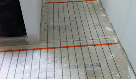
BATHROOM DESIGNWarm Up Your Bathroom With Heated Floors
If your bathroom floor is leaving you cold, try warming up to an electric heating system
Full Story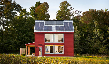
GREEN BUILDINGGoing Solar at Home: Solar Panel Basics
Save money on electricity and reduce your carbon footprint by installing photovoltaic panels. This guide will help you get started
Full Story
KITCHEN APPLIANCESFind the Right Cooktop for Your Kitchen
For a kitchen setup with sizzle, deciding between gas and electric is only the first hurdle. This guide can help
Full Story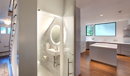
BATHROOM DESIGNLight-Up Mirrors Offer Bright Design Solutions
If you're taking a dim view of a problem bathroom area, try the flash of design brilliance that is the electric mirror
Full Story
LIFEHow to Prepare for and Live With a Power Outage
When electricity loss puts food, water and heat in jeopardy, don't be in the dark about how to stay as safe and comfortable as possible
Full Story
canguy