


craftsman dyt 4000
chrissymustang
14 years ago
Sort by:Oldest
Comments (31)
Related Stories
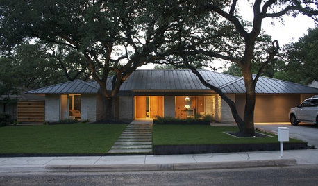
ARCHITECTURERoots of Style: Ranch Architecture Roams Across the U.S.
Great remodeling potential and generously spaced sites make ranch homes ever popular. Is one of the many variations right for you?
Full Story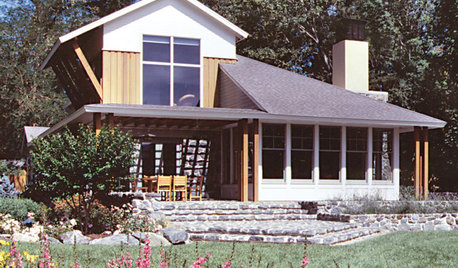
REMODELING GUIDES10 Elements of the Just-Right House
The World Series, Moneyball and the smart house: The case for smaller homes rich in character and function over the big and bland
Full Story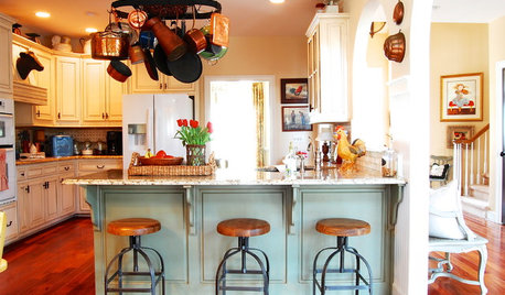
HOUZZ TOURSMy Houzz: French Country Meets Southern Farmhouse Style in Georgia
Industrious DIYers use antique furniture, collections and warm colors to cozy up their traditional home
Full Story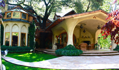
HOUZZ TOURSMy Houzz: Enchanting Nature-Inspired Home in Ojai
Organic shapes, art nouveau and all things nature influence an architect while designing his family's home on a spacious plot in California
Full Story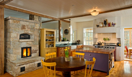
FARMHOUSESHouzz Tour: A LEED Platinum Home With Farmhouse Style
Equally charming and efficient, this pad in upstate New York houses a dance studio, a music room and plenty of warm, inviting living space
Full Story
FURNITUREHolding Out for Quality
Cheap furniture has its place, but more shoppers are waiting to invest for the long haul
Full Story
FIREPLACES12 Hot Ideas for Fireplace Facing
From traditional brick to industrial steel, there’s a fireplace cladding here to light up your design
Full Story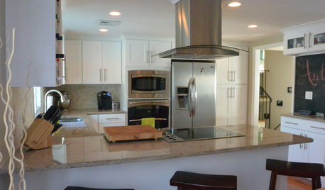
BEFORE AND AFTERSA ‘Brady Bunch’ Kitchen Overhaul for Less Than $25,000
Homeowners say goodbye to avocado-colored appliances and orange-brown cabinets and hello to a bright new way of cooking
Full Story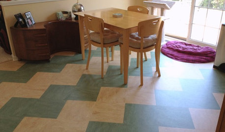
REMODELING GUIDESLinoleum, the All-Purpose Flooring Wonder
Dashing in a rainbow of colors, able to be cleaned with ease and courteous to budgets everywhere, linoleum is a super choice for floors
Full Story
DECORATING GUIDESSecrets to Shopping Craigslist
Frustrated with your results nabbing Craigslist treasures? This hard-earned wisdom will help you bring that perfect piece home
Full StorySponsored
More Discussions
rustyj14
mownie
Related Discussions
CRAFTSMAN dyt4000
Q
craftsman dyt 4000 tries to turn over then dies
Q
Lawn Tractor Not Starting - Craftsman DYT 4000
Q
Craftsman DYT4000 wont start
Q
chrissymustangOriginal Author
mownie
chrissymustangOriginal Author
mownie
chrissymustangOriginal Author
mownie
chrissymustangOriginal Author
bill_kapaun
chrissymustangOriginal Author
mownie
chrissymustangOriginal Author
mownie
chrissymustangOriginal Author
mownie
chrissymustangOriginal Author
mownie
chrissymustangOriginal Author
mownie
chrissymustangOriginal Author
mownie
chrissymustangOriginal Author
chrissymustangOriginal Author
mownie
chrissymustangOriginal Author
mownie
chrissymustangOriginal Author
mownie
mownie
mownie