


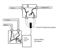
Where to tap into my range hood wiring to drive my makeup air damper?
HU-247834317
3 years ago
last modified: 3 years ago
Featured Answer
Comments (54)

kaseki
3 years agolast modified: 3 years agoDavidR
3 years agoRelated Discussions
Make-up Air - Please explain what I need to tell my contractors
Comments (6)See Martin Holladay's article. If you don't get makeup air from a dedicated intake, it will be drawn through all the air leaks in your home and possibly even backdrafting CO from the furnace and water heater if these are not closed units. Though I know you're looking for a cheap answer, I'd suggest finding a more educated HVAC designer with commercial experience to be safe. However, if you don't run the exhaust all out all the time there may be no need for makeup air. We had a 700 cfm unit that was only run full throttle when my spouse cooked fish and offal. I just cracked open a patio door and all was OK....See MoreNeed Advice - Kitchen Hood/Makeup Air
Comments (42)Any time the flow of air (or part of the air) has to change its velocity vector (direction and/or speed), even slightly, work is done on the air, and this requires either heating or force times distance. Pressure is force over area. Velocity change occurs not only when a duct bends, but when there is turbulence in the duct or at the duct walls, or when the air is forced through a filter, around baffles, etc. Thus, there are many ways that pressure drops occur along a flow path. If not, one could blow through a straw without having to build up pressure in one's mouth. I use a large (three-foot-square) vaned ceiling diffuser to introduce MUA into a hallway adjunct to the kitchen. The diffuser is about 18 feet from the edge of the hood. This configuration was the best option relative to where I could take the air from the roof area. It is my expectation that by the time the air gets to the vicinity of the hood it is flowing relatively smoothly and low in velocity due to the size and length of the hall. Certainly other approaches would work for other kitchens depending on where the air is taken from and how a house is architected. Test kitchens use a porous diffuser panel in an adjacent wall to the hood under test. I am sure that from a functional point of view, MUA flowing out from enough toe-kick area would also work, so long as it wasn't somehow directed at the stove. For example, if a cooktop were on an island, and the entire toe-kick area were grilled using a set of registers, the MUA would flow out and then up in a way that did not disturb the rising effluent from the pans. Even down flow behind a refrigerator can work if the path behind and underneath the refrigerator is relatively open (several times the area of the supplying duct.) Never forget that perfect is the enemy of good enough, and what we are trying to accomplish is good enough capture of grease, moisture, and odor. Good enough is also user dependent, so not everyone needs to put up with the compromises that a nearly perfect MUA system would impose on a house. So, my best advice is to find a way to introduce the air that doesn't blow at the cooking zone and disturb the natural rise of the cooking effluent. kas...See Moremakeup air vent ~5' from range?
Comments (7)Although I don't do it myself for various architectural reasons, I am a fan of basement entering MUA because a room heater of sufficient power can usually be installed there (electric or hydronic) to temper the air without having to design specifically for duct air heating. However, toe kick entry into the kitchen needs to be large enough to not be a major pressure loss in the MUA system. I.e., sufficient toe kick area, perhaps equivalent to the hood entry aperture area, needs to be provided. Also, the toe kicks used shouldn't be right onto the cook's toes. There was a forum member here who had a turbulence problem with the toe kick MUA entry blowing across a narrow inter-counter gap to hit another island/peninsula where it was directed up next to the hood space. The turbulence at the hood caused significant plume disturbance to the point that capture was seriously disrupted. That all said, if the cabinet dump out of the bottom were via diffusers that could throw the air across the room instead of at the hood, then room mixing and air slowing would be possible. Nonetheless, if a basement path is the only one that can be heated, I would plan for the future if I were you and use the basement. Note that if a basement wall is available for a duct, then a 10-inch duct placed in the wall with a 45-degree or greater cut outside to provide a rain shield would do as a basement entry. It will need a damper either balanced for low pressure opening or electrically controlled by sensing hood air flow (or hood motor power). A screen should be placed at the entry....See MoreMakeup Air For Range Hood
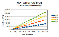
Comments (3)Is this a passive (no blower) or an active (blower) MUA? Do you have any combustion appliances that take air from inside any part of the house connected to the kitchen? If not, then the pressure loss in the MUA from using a decent air filter will not matter, safety wise. Please better explain the path the MUA would take from outside to kitchen with option 1. I would like to be sure that I understand the concept. Also, do you need to heat the MUA? (See chart.) Dumping MUA into a basement or laundry room provides a means for having a heating system (e.g., hydronic or electric Dayton wall unit) in the room with its own thermostat, eliminating a complexity in the MUA system. In either option, MUA entering the kitchen must not cause excessive turbulence or cross drafts in the area between cooktop and hood entry aperture. Commercial MUA dumped at the floor seems to work OK with commercial style cooking devices (which are mop-spaced off of the floor). However, some home ranges prohibit air entry below the unit. This needs to be checked. Else, air from either source may have to be passed into more remote (from the cooktop) registers/diffusers and allowed to spread out into the kitchen volume. Option 2 needs to be considered from a dust into the kitchen concern point of view. In any case, the air intake outside should be higher than ground level, with the duct going down to the level where it would enter the basement....See MoreHU-247834317
3 years agoHU-247834317
3 years agoDavidR
3 years agokaseki
3 years agolast modified: 3 years agoHU-247834317
3 years agokaseki
3 years agoDavidR
3 years agoHU-247834317
3 years agolast modified: 3 years agoDavidR
3 years agolast modified: 3 years agoweedmeister
3 years agoHU-247834317
3 years agolast modified: 3 years agoMichelle misses Sophie
3 years agolast modified: 3 years agoDavidR
3 years agolast modified: 3 years agoHU-247834317
3 years agoDavidR
3 years agoHU-247834317
3 years agokaseki
3 years agolast modified: 3 years agoHU-247834317
3 years agoDavidR
3 years agomtvhike
3 years agoDavidR
3 years agolast modified: 3 years agokaseki
3 years agoDavidR
3 years agolast modified: 3 years agokaseki
3 years agoHU-247834317
3 years agokaseki
3 years agolast modified: 3 years agoweedmeister
3 years agoHU-247834317
3 years agokaseki
3 years agolast modified: 3 years agoHU-247834317
3 years agoweedmeister
3 years agoHU-247834317
3 years agokaseki
3 years agoHU-247834317
3 years agoHU-247834317
3 years agolast modified: 3 years ago
opaone
3 years agolast modified: 3 years agokaseki
3 years agokaseki
3 years agolast modified: 3 years agoHU-247834317
3 years agokaseki
3 years agoHU-247834317
3 years agokaseki
3 years agoHU-247834317
3 years agokaseki
3 years agoopaone
3 years agolast modified: 3 years agoHU-247834317
3 years agoopaone
3 years ago
Related Stories
KITCHEN APPLIANCESDisappearing Range Hoods: A New Trend?
Concealed exhaust fans cut visual clutter in the kitchen
Full Story
KITCHEN APPLIANCESWhat to Consider When Adding a Range Hood
Get to know the types, styles and why you may want to skip a hood altogether
Full Story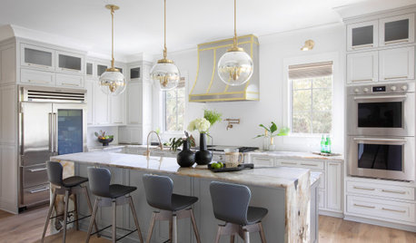
KITCHEN DESIGNDesigner Tips for Range Hoods, Appliances and Lighting
Learn how to get your microwave height just right, what kind of bar stool will be most comfortable and more
Full Story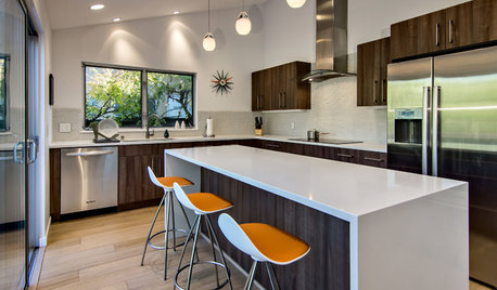
REMODELING GUIDESWhere to Splurge, Where to Save in Your Remodel
Learn how to balance your budget and set priorities to get the home features you want with the least compromise
Full Story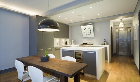
KITCHEN DESIGNHow to Choose the Right Hood Fan for Your Kitchen
Keep your kitchen clean and your home's air fresh by understanding all the options for ventilating via a hood fan
Full Story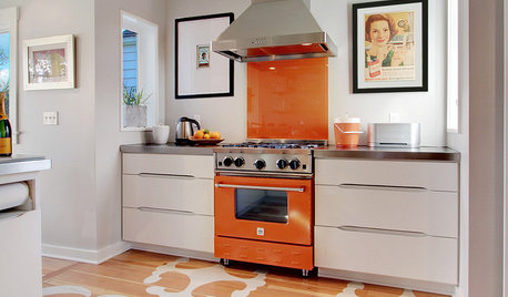
HOUSEKEEPINGHow to Clean Your Range and Oven
Experts serve up advice on caring for these kitchen appliances, which work extra hard during the holidays
Full Story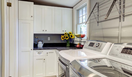
THE HARDWORKING HOMEWhere to Put the Laundry Room
The Hardworking Home: We weigh the pros and cons of washing your clothes in the basement, kitchen, bathroom and more
Full Story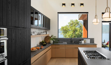
KITCHEN DESIGNWhere Should You Put the Kitchen Sink?
Facing a window or your guests? In a corner or near the dishwasher? Here’s how to find the right location for your sink
Full Story
CHRISTMASGift Giving the Simple-ish Way
If buying holiday gifts drives you to the spiked holiday punch, try these easier but still rewarding traditions
Full Story
KITCHEN DESIGNA Cook’s 6 Tips for Buying Kitchen Appliances
An avid home chef answers tricky questions about choosing the right oven, stovetop, vent hood and more
Full Story
HU-247834317Original Author