


Disherwasher, Disposal Wiring on One Outlet
nuckphoto
14 years ago
Sort by:Oldest
Comments (21)
Related Stories
GREAT HOME PROJECTSPower to the People: Outlets Right Where You Want Them
No more crawling and craning. With outlets in furniture, drawers and cabinets, access to power has never been easier
Full Story
KITCHEN DESIGN8 Kitchen Design Tips for Foodies
If you own at least one pricey knife and have a slew of kitchen tools, you’ll want to read this
Full Story
GREEN BUILDINGOff the Grid: Ready to Pull the Plug on City Power?
What to consider if you want to stop relying on public utilities — or just have a more energy-efficient home
Full Story
KITCHEN DESIGNHouzzers Say: Top Dream Kitchen Must-Haves
Tricked-out cabinets, clean countertops and convenience top the list
Full Story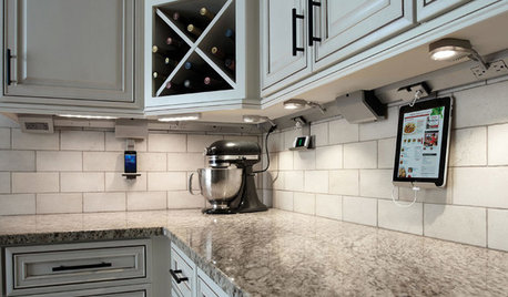
KITCHEN DESIGN7 Awesome Add-ons for Kitchen Cabinets
Useful gadgets, docks for your devices, extra lighting ... when it comes to cabinets, do look down
Full Story
LIGHTINGHow to Choose the Right Solar Lights
Learn about different types of outdoor solar lights, where to use them and why you might want to avoid the bargain bin
Full Story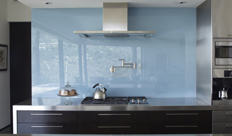
KITCHEN DESIGNThe Future of Backsplashes
Grout is out. Continuous sheets of glass, stone, metal and porcelain are saving cleaning time and offering more looks than ever
Full Story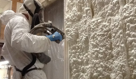
MATERIALSInsulation Basics: What to Know About Spray Foam
Learn what exactly spray foam is, the pros and cons of using it and why you shouldn’t mess around with installation
Full Story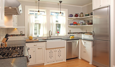
KITCHEN DESIGNThe 100-Square-Foot Kitchen: Farm Style With More Storage and Counters
See how a smart layout, smaller refrigerator and recessed storage maximize this tight space
Full Story
KITCHEN DESIGNHow to Design a Kitchen Island
Size, seating height, all those appliance and storage options ... here's how to clear up the kitchen island confusion
Full Story

terribletom
brickeyee
Related Discussions
Installing an outlet for garbage disposal on a 120V/240 multi cir
Q
Garbage Disposal wiring help
Q
dishwasher/disposal wiring
Q
Dishwasher & Garbage Disposal Wiring Question
Q
nuckphotoOriginal Author
terribletom
brickeyee
Ron Natalie
terribletom
terribletom
Ron Natalie
nuckphotoOriginal Author
brickeyee
terribletom
nuckphotoOriginal Author
terribletom
nuckphotoOriginal Author
terribletom
nuckphotoOriginal Author
nuckphotoOriginal Author
terribletom
nuckphotoOriginal Author
hendricus